
Views: 0 Author: Site Editor Publish Time: 2026-07-28 Origin: Site


Operating a heavy-duty truck or trailer relies on exact ride height calibration. An incorrect ride height accelerates driveline wear, damages costly air springs, and heavily compromises vehicle handling. You might assume adjusting a suspension component requires minimal effort. While adjusting a leveling valve is mechanically straightforward, doing it blindly is highly dangerous. Proceeding without exact manufacturer specifications or proper safety protocols proves completely ineffective. Mechanics face fatal risks if an air suspension system suddenly deflates during inspection.
You must approach this maintenance task with extreme precision. Respecting the vehicle's pneumatic systems ensures a secure working environment. Our objective here is definitive. We provide a clear, standard operating procedure (SOP) for safely checking and adjusting your height control valve.
You will also learn a reliable framework to evaluate component health. We will help you determine if the valve is failing and requires immediate replacement. By following these guidelines, you can ensure peak suspension performance and maximize safety on the highway.
Safety is absolute: Never adjust a leveling valve without securely blocking the vehicle chassis; sudden air suspension deflation can be fatal.
Precision matters: Adjustments must be based on exact OEM ride height measurements, typically measured from the axle center to the frame bottom.
Know when to replace: If a leveling valve exhibits continuous air leaks, delayed response times (over 10 seconds), or erratic leveling, adjustment will not fix it—replacement is necessary.
Fleet managers often view misaligned ride height as just a minor driver comfort issue. In reality, ignoring this parameter directly impacts your fleet maintenance costs. Driving out of spec causes premature U-joint failure. It also induces severe suspension fatigue over time. The driveline angles shift drastically when the ride height is wrong. This angular shifting creates harmful vibrations across the entire chassis. These vibrations destroy wheel bearings and transmission seals. Recognizing the early warning signs helps you avoid expensive, unexpected breakdowns.
Mechanics should look for specific visual and mechanical symptoms. Diagnosing the issue early prevents catastrophic air spring blowouts. Consider these common signs of a failing or misadjusted system:
You experience a harsh, rigid ride quality over minor bumps.
The suspension frequently bottoms out when driving over standard road irregularities.
The trailer or truck leans noticeably to one side. This leaning usually occurs on multi-valve systems.
You feel severe driveline vibration due to incorrect pinion angles.
You hear continuous hissing from the exhaust port after the vehicle settles.
A perfectly functioning Leveling Valve maintains proper chassis height automatically. When it drifts out of calibration, it continuously wastes compressed air. You burn more fuel to keep the engine air compressor running. Drivers also complain about severe physical fatigue from the rough ride. Ultimately, proactive diagnosis keeps your vehicle safely on the road.
Safety comes first when working on heavy-duty air suspension systems. Most roadside accidents during suspension maintenance occur due to a sudden loss of air pressure. Do not rely on hydraulic jacks alone. Never trust the air system to hold the vehicle up. A sudden valve release will crush anyone working underneath the chassis. Experienced technicians know gravity never forgives poor preparation.
You must gather specific equipment before starting the job. Professional mechanics strictly adhere to this required tools setup:
Heavy-duty jack stands rated strictly for the vehicle's gross weight.
Solid chassis blocks for redundant safety support.
A reliable tape measure or digital caliper for precision measurements.
Appropriate wrenches for the linkage rod and adjustment nuts.
Heavy-duty wheel chocks to prevent accidental rolling.
OSHA-approved safety glasses to protect against undercarriage debris.
Finding the Original Equipment Manufacturer (OEM) specification is absolutely crucial. We must emphasize there is no universal measurement for ride height. Every chassis requires specific, engineered parameters. You must locate the ride height parameter directly from the chassis or suspension manufacturer. Brands like Hendrickson or Peterbilt publish specific service manuals detailing these exact numbers.
Information Source | Where to Find It | What to Look For |
|---|---|---|
Chassis Data Plate | Driver door jamb or frame rail | Base ride height measurement in inches |
Suspension Manual | Manufacturer website or dealership | Specific axle-to-frame distance specs |
Technical Bulletins | Fleet maintenance web portals | Updates on neutral dead band angles |
Never guess the ride height dimension. Measure exactly as the manufacturer instructs. Proper measurement ensures maximum safety and extends driveline health.
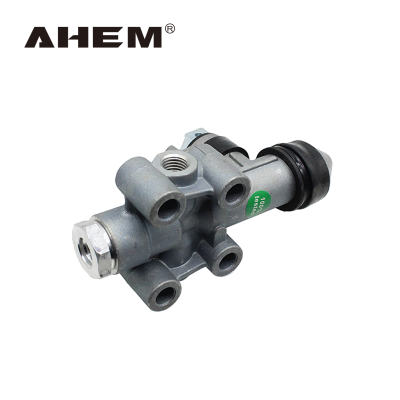
Executing a proper adjustment demands patience and strict attention to detail. Do not rush these procedures. You want a consistent, highly repeatable result across the suspension system.
First, park the vehicle on a hard, completely level surface. Uneven ground skews your measurements entirely. Place wheel chocks firmly against the tires. Start the engine and build the air system to full operational pressure. This pressure typically ranges between 100 and 120 PSI. Once the system reaches maximum pressure, shut off the engine. Measure the current ride height exactly as specified by the OEM. Record this baseline measurement carefully for comparison.
Safely block the frame using your heavy-duty jack stands. Locate the height control component. You usually find it mounted securely to the frame rails. It connects directly to the axle via a vertical linkage arm. Once located, inspect the surrounding hardware for severe rust. Loosen the adjustment nut or clamp on the linkage rod. On some commercial models, you loosen the valve lever arm itself. This design varies significantly by manufacturer.
You are now ready to alter the ride height. Make sure you fully understand the airflow direction before moving anything.
To increase height, move the lever arm slightly upward. This action allows pressurized air to flow directly into the springs.
To decrease height, move the lever arm slightly downward. This exhausts air out of the system safely.
Always adjust the linkage in tiny increments. Try moving the arm just 1/4 inch at a time. Wait for the air system to respond. Let it settle completely before moving it again. The thermodynamics of compressed air cause slight delays in physical movement.
Tighten the adjustment nut firmly to the proper torque specs. Do not overtighten it. Overtightening will crush the linkage components. Remove the frame blocks carefully. Next, dump the suspension air completely using the cabin switch. Let it refill automatically to test the valve’s repeatability. Re-measure the ride height. If the measurement is inconsistent after cycling, the internal mechanism is likely compromised. Inconsistency indicates mechanical wear, not just a poor adjustment.
Adjusting a worn-out component wastes valuable labor hours. You need to know exactly when the part is beyond saving. We evaluate component failure across a specific physical dimension. Let us look at the definitive signs of total mechanical failure.
The "Dead Zone" Test
A healthy height control valve features a built-in neutral dead band. This dead band usually spans 1.5 to 5 degrees of motion. It prevents the air system from overreacting to normal road bumps. Test this by moving the linkage slightly by hand. If the arm has to move excessively before air flows, the internal seals are severely worn. You must replace the unit immediately to restore safety.
Constant Exhaust Leaks
Listen closely to the exhaust port in its neutral position. If it continuously exhausts air, the ceramic or rubber internal discs are heavily scored. They degrade over time due to moisture and grit entering from the air tanks. A continuous leak means the component cannot hold necessary pressure. Draining your air tanks regularly helps prevent this internal scoring.
Linkage Wear
Inspect the rubber bushings and the linkage rod closely. Bent rods cause geometric mathematical errors in the suspension. Rotted bushings create sloppy slack in the physical movement. These defects will cause erratic ride heights even with a perfectly functioning main unit. Replacing just the linkage often solves the tracking problem quickly.
Symptom Observed | Primary Cause | Recommended Action |
|---|---|---|
Erratic Height Changes | Worn linkage bushings or bent rod | Replace linkage assembly immediately |
Constant Air Hissing | Scored internal ceramic/rubber discs | Replace the entire main unit |
Slow Response Time | Wide dead band due to worn seals | Test dead zone; replace if failed |
System Leans to One Side | Pinched air line or failing bag | Inspect lines and suspension bags thoroughly |
If replacement is required, fleets and owner-operators must evaluate their options carefully. Choosing the right component prevents future roadside failures. You face several solution categories on the heavy-duty parts market today.
OEM vs. Quality Aftermarket
Assess the initial upfront cost versus the long-term warranty benefits. High-quality aftermarket options often meet or exceed original OEM specifications. They usually do so at a much lower price point. However, buyers must verify port configurations very carefully. Buying a cheap, poorly manufactured knockoff risks catastrophic suspension failure at highway speeds. Stick to trusted brands known for strict quality control.
Key Specs to Match
When sourcing a new part, match these exact mechanical specifications:
Port Sizes: Ensure the supply, delivery, and exhaust ports match your existing air lines perfectly. The standard commercial sizes are usually 1/4" or 3/8" NPT threads. Mismatched threads will cause severe air leaks.
Dump Feature: Determine if your air system requires an integrated dump feature. These can be normally open or normally closed designs. This feature lowers the truck or trailer safely at warehouse loading docks.
Time Delay: Some heavy-duty systems require a specialized time-delay mechanism. This prevents the air from cycling constantly on rough, unpaved roads. Ensure the replacement part matches this specific dampening spec.
Matching these specifications ensures a seamless and fast installation process. It eliminates the need for messy adapters or return shipments.
Correctly adjusting your suspension requires strict adherence to safety blocking protocols. You must always use exact OEM measurements. You also need significant patience during the pneumatic adjustment cycles. Rushing the process guarantees an inaccurate ride height. If your unit fails the repeatability test, leaks air continuously, or the linkage is seized, stop adjusting immediately. Continuing to force it will result in severe structural suspension damage.
Protect your fleet by replacing worn parts as soon as symptoms appear. Browse our extensive inventory of heavy-duty components, exact-fit linkages, and air suspension accessories to restore your vehicle's factory ride height. Alternatively, you can contact our technical team to verify your specific part numbers today.
A: None. In the neutral position, a healthy height control valve should hold air securely. Any continuous hissing indicates internal seal failure. You should replace the component immediately to prevent compressor wear.
A: If your truck uses a dual-valve system, they must be adjusted in tandem. If it uses a single valve, a lean indicates a pinched air line, a leaking air bag on one side, or an unlevel parking surface during adjustment.
A: There is no strict mileage interval, but they typically last 5 to 7 years depending on operating environments. Corrosion, freezing moisture in the air lines, and extreme physical vibration are the primary causes of failure.
