
Views: 0 Author: Site Editor Publish Time: 2026-10-16 Origin: Site


You are hauling 80,000 pounds down a steep six percent grade. In that critical moment, the only thing standing between a safe descent and a catastrophic highway accident is the integrity of your air brake system. At the functional core of this complex pneumatic network operates the brake actuator. This highly engineered component is specifically designed to convert compressed air into the raw mechanical force necessary to halt massive payloads.
Over extended operational periods, internal rubber diaphragms inevitably wear out. Coiled steel springs lose their structural tension. Exterior metal housings succumb to environmental rust and road salt. These degradation factors frequently lead to dangerous air pressure leaks or total mechanical failure. Knowing how to swap out this vital canister safely and efficiently is an essential technical skill for fleet maintenance personnel, owner-operators, and heavy-duty diesel mechanics.
This procedure involves interacting with highly pressurized internal springs and heavy commercial machinery. Executing it incorrectly can lead to severe physical injury. This comprehensive guide will walk you through the objective steps required for a safe swap. From identifying a failing unit and gathering the specialized tools to safely caging the power spring, we cover the real-world practicalities needed to restore your braking system to optimal Department of Transportation standards.
Safety is Non-Negotiable: Never attempt to open, alter, or remove a spring brake canister without properly caging the internal power spring first. The internal parking spring holds thousands of pounds of kinetic force.
Identify the Correct Replacement: Pneumatic actuators are manufactured in varying types and volumetric sizes. Always match the replacement exactly to the Original Equipment Manufacturer specifications of your specific axle.
Preparation is Mandatory: Chocking the vehicle wheels securely, systematically draining the primary and secondary air tanks, and staging the correct tools are mandatory prerequisites before initiating the removal process.
Full Unit Replacement Priority: Replacing solely the internal rubber diaphragm remains mechanically possible on some front service units. However, replacing the entire sealed unit is empirically safer and yields higher long-term reliability.
Post-Installation Validation: Always perform a rigorous soapy water leak test. Manually adjust the slack adjuster to ensure proper pushrod stroke travel before returning the vehicle to active service.
Before examining the exact procedures for a replacement, it is fundamentally important to understand the component's mechanical purpose. You will encounter different structural variations when sliding under a commercial chassis.
Functionally, the device acts as a pneumatic-to-mechanical cylinder. When the operator depresses the service pedal in the cab, regulated compressed air travels through the lines and fills the canister housing. This pressurized air forces a heavy-duty rubber diaphragm outward. Specifically, the moving diaphragm pushes a steel rod outward. This linear motion turns the slack adjuster and rotates the S-cam. Ultimately, this forces the friction shoes against the rotating steel drum to stop the wheel.
Commercial vehicles utilize two distinct classifications of these actuators depending on their axle location. Service units are typically mounted on the front steer axles. These units contain only a single pneumatic section that applies the mechanical friction exclusively when pressurized air is actively introduced by the driver.
Spring units, often referred to as piggybacks, are predominantly installed on drive axles and trailer axles. These complex components feature two distinct sections. They have a standard service section and a secondary parking or emergency section. The emergency section houses a massive, tightly coiled steel spring. This spring mechanically applies the stopping force when system air pressure is intentionally or accidentally released.
These components are universally categorized by their effective internal diaphragm area, measured in square inches. Upgrading to high-quality replacements ensures longevity. Premium units often feature 8-gauge steel housings and advanced ozone-resistant rubber compounds capable of withstanding 120 PSI continuous operating pressures.
To assist in identifying the correct hardware for your specific commercial chassis, refer to the following standard engineering specifications.
Chamber Type | Primary Application | Effective Area | Standard Legal Stroke Limit |
|---|---|---|---|
Type 20 | Front Steer Axles | 20 sq. inches | 1.75 inches |
Type 24 | Light Drive Axles / Steer Axles | 24 sq. inches | 1.75 inches |
Type 30 | Heavy Drive Axles / Trailers | 30 sq. inches | 2.00 inches |
Type 30/30 Long Stroke | Heavy-Duty Trailers / Severe Service | 30 sq. inches | 2.50 inches |
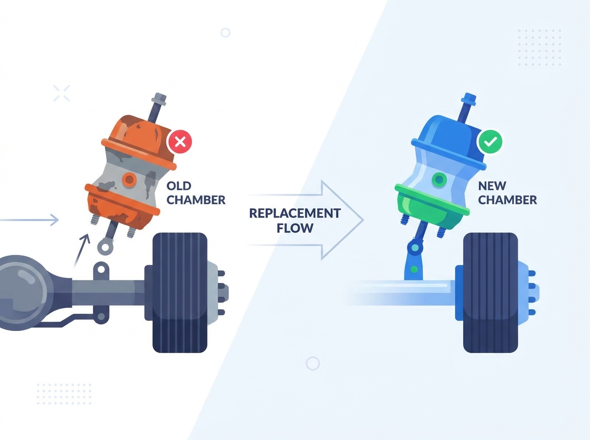
Proactively identifying a deteriorating unit can prevent costly roadside breakdowns. It also shields fleets from severe inspection penalties. A single out-of-service violation costs significantly more than a proactive hardware swap. Fleet managers and operators should monitor vehicles for the following empirical warning signs.
Listen closely after shutting off the engine. If you detect a continuous, distinct hissing sound emanating from the wheel end assembly after releasing the service pedal, the internal rubber diaphragm has likely developed a structural tear. Air bypassing the diaphragm severely compromises stopping efficiency.
If the commercial vehicle exhibits a tendency to pull sharply to one side during deceleration, a canister may be mechanically binding. Telemetry data showing a noticeable delay in stopping power also points to internal binding. This prevents the pushrod from deploying to its full required stroke length.
Routine visual inspections must include the exterior housing. Heavy localized rust, deep structural dents, or a visibly bent pushrod indicate that the structural integrity is fatally compromised. When dealing with heavily corroded components that threaten fleet safety, engaging comprehensive fleet maintenance services for a thorough axle inspection is often the most prudent operational decision.
Executing this procedure requires specific, heavy-duty mechanical tools. Attempting this work with improper equipment increases the risk of component damage and personal injury.
Before you even slide under the chassis, ensure you have heavy-duty commercial wheel chocks. These are mandatory to prevent vehicle rollaway. Furthermore, wear safety goggles to protect your eyes from falling rust debris, alongside thick impact-resistant mechanic gloves. If axle lifting is deemed necessary, only use heavy-duty jack stands rated for commercial vehicle weights.
You will need a caging T-bolt complete with its corresponding nut and washer. This is often supplied attached to the side housing of the new replacement unit. Additionally, gather a comprehensive set of open-end wrenches and specialized line wrenches. Line wrenches are mandatory because standard open-end wrenches will strip soft brass fittings. Vise grips, needle-nose pliers, an industrial tape measure, a hacksaw, pneumatic thread sealant, and a soapy water spray bottle will round out your toolkit.
Within the context of heavy-duty pneumatics, this represents the single most critical safety protocol in the entire maintenance procedure. If you are interacting with a dual-chamber unit, you must mechanically cage the power spring prior to unbolting the hardware.
The parking section houses a heavy-duty coiled steel spring. This is not just a standard coil. It remains compressed under approximately 2,000 to 3,000 pounds of constant kinetic force. If the structural clamp band is prematurely removed, the housing can explode outward with lethal velocity. A rusted housing fracturing during removal without the spring being securely caged yields the same catastrophic result.
Carefully remove the rubber or plastic dust cap located at the very back center of the housing. Next, insert the specialized caging T-bolt directly into the exposed access hole. Push the bolt inward until it bottoms out. Twist it exactly one quarter-turn to securely lock the T-head into the internal pressure plate receptacle.
Slide the heavy-duty washer over the bolt and thread the retaining nut onto the exposed threads. Using a properly sized wrench, systematically tighten the nut. As the nut threads downward, it physically pulls the internal spring backward. This safely contains the mechanical pressure. Stop tightening immediately when the spring is fully compressed. Over-torquing will fracture the internal pressure plate.
Once the commercial vehicle is entirely secured and the hazardous spring is safely caged, technicians can proceed with the physical swap. Expect to encounter grit, grime, and stubborn bolts during this process.
Park the vehicle on a verified flat, stable concrete surface. Chock the tires securely on both sides of the axle so the chassis cannot shift. Open the petcocks to drain the primary and secondary air tanks completely. This removes all residual pneumatic pressure from the system. Depressurizing prevents sudden, dangerous bursts of compressed air when disconnecting the delivery lines.
Using appropriately sized line wrenches, carefully unscrew the air lines connected to the canister ports. A practical tip from veteran mechanics is to use colored electrical tape to distinctly mark the primary service line and the emergency line. Crossing these lines during reinstallation will cause complete system malfunction.
Locate the clevis assembly connecting the pushrod to the slack adjuster arm. Use pliers to straighten and remove the cotter pin securing the main clevis pin. Once the cotter pin is removed, tap the clevis pin out of the assembly. This effectively decouples the canister from the mechanical linkage.
Locate the two large mounting nuts that secure the housing to the welded axle bracket. If the environment has been harsh, use a wire brush on those mounting studs before hitting them with penetrating oil. Using a heavy-duty wrench or impact driver, unbolt these nuts. Once free, carefully support the heavy unit and pull it directly away from the mounting bracket. If the mounting studs are completely seized, utilizing a professional heavy-duty repair service equipped with cutting torches may be required.
Prior to installation, place the old canister next to the new unit. Measure the exposed pushrod on the old hardware with exact precision. If the new canister does not feature a pre-cut rod, use a hacksaw or angle grinder to cut the new pushrod to the exact same dimensional length. Thread the locking nut and clevis onto the newly cut pushrod.
Slide the new mounting studs through the axle bracket. Install the washers and tighten the mounting nuts to the manufacturer's specific torque rating. Finally, reconnect the clevis to the slack adjuster using the clevis pin and a brand-new cotter pin.
Apply approved pneumatic thread sealant to the brass air line fittings. Thread them into their designated ports and tighten them securely. Once the mechanical installation is verified, start the vehicle engine. Allow the air compressor to build the system up to standard operating pressure, which is typically 120 PSI.
With the system pressurized, carefully unscrew the nut on the caging bolt. Twist the T-bolt a quarter-turn to unlock it, and remove it from the housing to un-cage the power spring.
Fleet operators frequently analyze whether they should rebuild a failing canister by simply replacing the internal rubber diaphragm rather than procuring an entirely new assembly. Replacing solely the diaphragm is generally considered acceptable industry practice only on the front steer units lacking the high-tension parking spring. It is a cost-effective measure if the exterior metal housing and internal pushrod plate are completely free of structural rust and deformation.
In contrast, opening a sealed dual-chamber unit to replace a diaphragm introduces extreme safety hazards. Empirical data shows that if the primary diaphragm has ruptured, the internal return springs, pushrod seals, and housing integrity are likely nearing the end of their lifecycle regardless. Replacing the entire sealed assembly guarantees maximum safety compliance and minimizes future vehicle downtime.
The maintenance procedure is not finalized simply because the hardware is bolted to the axle. Rigorous post-installation testing ensures the commercial vehicle is legally compliant and safe for highway operation. Integrating reliable commercial brake chamber solutions ensures these tests pass on the first attempt.
Start the truck and let the air compressor build full cutout pressure. Firmly apply the service pedal. While the system is under active load, spray a soapy water solution generously around the brass air line fittings and the exterior clamp bands of the newly installed unit. The formation of expanding bubbles indicates an active air leak that requires immediate fitting adjustment or re-sealing.
Technicians must verify the operational stroke. With the system fully applied at 90 to 100 PSI, measure the distance the pushrod travels outward. The stroke must not exceed the legal out-of-service limit strictly defined for that specific size. Adjust the automatic or manual slack adjuster accordingly to ensure optimal friction contact.
As commercial vehicle technology rapidly evolves, the fundamental approach to pneumatic maintenance is shifting from reactive repairs to proactive diagnostics. Recent industry trends highlight a growing reliance on smart actuators equipped with electronic stroke indicators and internal wear sensors. These advanced units communicate directly with the truck's telemetry system. They alert drivers to pushrod over-travel or minor air leaks long before a physical roadside inspection would catch them.
Furthermore, commercial vehicle safety enforcement is becoming increasingly data-driven. Inspectors utilize infrared cameras to detect cold wheel ends, instantly identifying a malfunctioning actuator. As supply chain demands push fleets harder, integrating predictive data analytics is rapidly becoming the industry standard. This technological shift helps operators avoid costly out-of-service violations and drastically minimizes unexpected highway downtime.
While swapping an actuator follows a logical mechanical progression, it is not an appropriate undertaking for untrained personnel lacking heavy-duty pneumatic experience. Modern commercial vehicles often feature advanced anti-lock braking systems, electronic stability control, and customized pneumatic routing. Managing a diverse fleet requires precision.
If the primary mounting bracket welded to the axle housing exhibits heavy rust, stress fractures, or bending, simply bolting on a new canister will not rectify the underlying structural failure. A certified professional will be required to perform structural welding on the axle bracket. For complex configurations or severe structural degradation, relying on expert fleet maintenance solutions ensures your systems remain perfectly synchronized and legally compliant.
Understanding how to maintain and replace pneumatic actuators is a vital part of heavy-duty truck maintenance. By recognizing the signs of failure early, respecting the immense kinetic power of the internal spring, and following a strict replacement procedure, you protect your fleet and the public. Always remember that when dealing with commercial vehicle stopping power, there is no room for shortcuts. Take your time, use the right tools, always cage the spring, and double-check your work with a rigorous leak test. Selecting high-quality engineered replacement parts ensures your rig remains safe, reliable, and ready for the demanding road ahead.
For a certified, experienced heavy-duty mechanic, replacing a standard commercial unit typically requires between 30 to 60 minutes per wheel end. However, if the mounting bracket bolts are heavily oxidized or mechanically seized to the axle housing, the extraction process may require cutting torches. This significantly extends the required labor time.
Absolutely not. Operating a commercial vehicle with an active pneumatic leak is exceptionally dangerous and constitutes a major out-of-service violation. A continuous air leak depletes the system's compressed air reserves. If pressure drops below critical thresholds, the emergency springs can automatically deploy while the vehicle is in motion, leading to a catastrophic loss of vehicular control.
The numeric designation directly refers to the effective surface area of the internal rubber diaphragm, measured in square inches. A Type 20 features 20 square inches of surface area and generates proportionally less mechanical force, making it suitable for front steer axles. A Type 30 features 30 square inches of area, generating significantly more stopping force, and serves as the standard specification for heavy-duty drive and trailer axles.
The unit is successfully caged when the specialized mechanical T-bolt is fully inserted into the rear access port, twisted 90 degrees to lock into the internal pressure plate, and the exterior retaining nut is tightened down. This physical action retracts the internal power spring and mechanically prevents the pushrod from extending, completely neutralizing the kinetic danger.
While federal regulations do not strictly mandate replacing them in pairs, it is universally recommended by certified mechanical engineers to replace them across the same axle simultaneously. Matching the age, spring tension, and diaphragm elasticity on both sides of the axle ensures that the mechanical force is applied perfectly evenly. This prevents the vehicle from dangerously pulling to one side during emergency deceleration.
To measure the stroke accurately, first ensure system air pressure is at a minimum of 90 to 100 PSI. Chock the wheels and release the parking brakes. Measure and record the distance from the face of the canister to the center of the clevis pin. Next, have an assistant fully depress the service pedal. Measure the distance to the exact same point on the clevis pin again. The difference between the two measurements is your operational stroke, which must be compared against standard legal limits.
If the service section diaphragm ruptures while driving, you will experience a severe loss of stopping power on that specific wheel end, and system air pressure will drop rapidly during application. If the failure causes a massive system-wide pressure loss dropping below 60 PSI, the tractor protection valve will trigger. This automatically deploys the massive internal parking springs on the drive and trailer axles, bringing the heavy vehicle to an abrupt, uncontrolled emergency stop in the middle of the roadway.
