
Views: 0 Author: Site Editor Publish Time: 2026-10-23 Origin: Site


Air brakes keep massive trucks safely under control on unpredictable roads. A hissing brake chamber is not a minor nuisance. It is a severe driving hazard. A compromised pneumatic system threatens fleet safety and your bottom line. Dealing with a spongy brake pedal? Sluggish stopping response? Brakes refusing to release? You are likely facing a chamber failure. This guide breaks down the repair process safely. We cover precise diagnostics and mandatory safety protocols for the highly dangerous spring brake. You will get step-by-step replacement instructions and actionable selection criteria.
Safety is Non-Negotiable: Never pry open the spring brake side without proper caging. The internal power spring holds massive potential energy. It causes fatal blunt-force injuries if released improperly.
Diagnosis is Key: Standard maintenance involves replacing a ruptured service diaphragm or swapping the entire piggyback unit. Accurately identifying the failure point saves valuable downtime.
Proper Caging is Mandatory: Manually caging the spring brake with a designated T-bolt is your absolute first physical step in any repair procedure.
Test After Repair: Always perform a comprehensive soap-and-water leak test. Recalibrate the slack adjusters to Department of Transportation specifications before returning the commercial vehicle to active service.
The commercial vehicle maintenance sector is rapidly shifting toward completely sealed and tamper-proof spring brake chambers. With the rise of Advanced Driver Assistance Systems, foundation brakes must react in milliseconds. A slight pressure drop from a rebuilt or micro-leaking chamber disrupts collision mitigation algorithms. Consequently, fleet managers now prioritize full piggyback replacements over field-rebuilding. This approach ensures strict regulatory compliance and maximizes vehicle uptime.
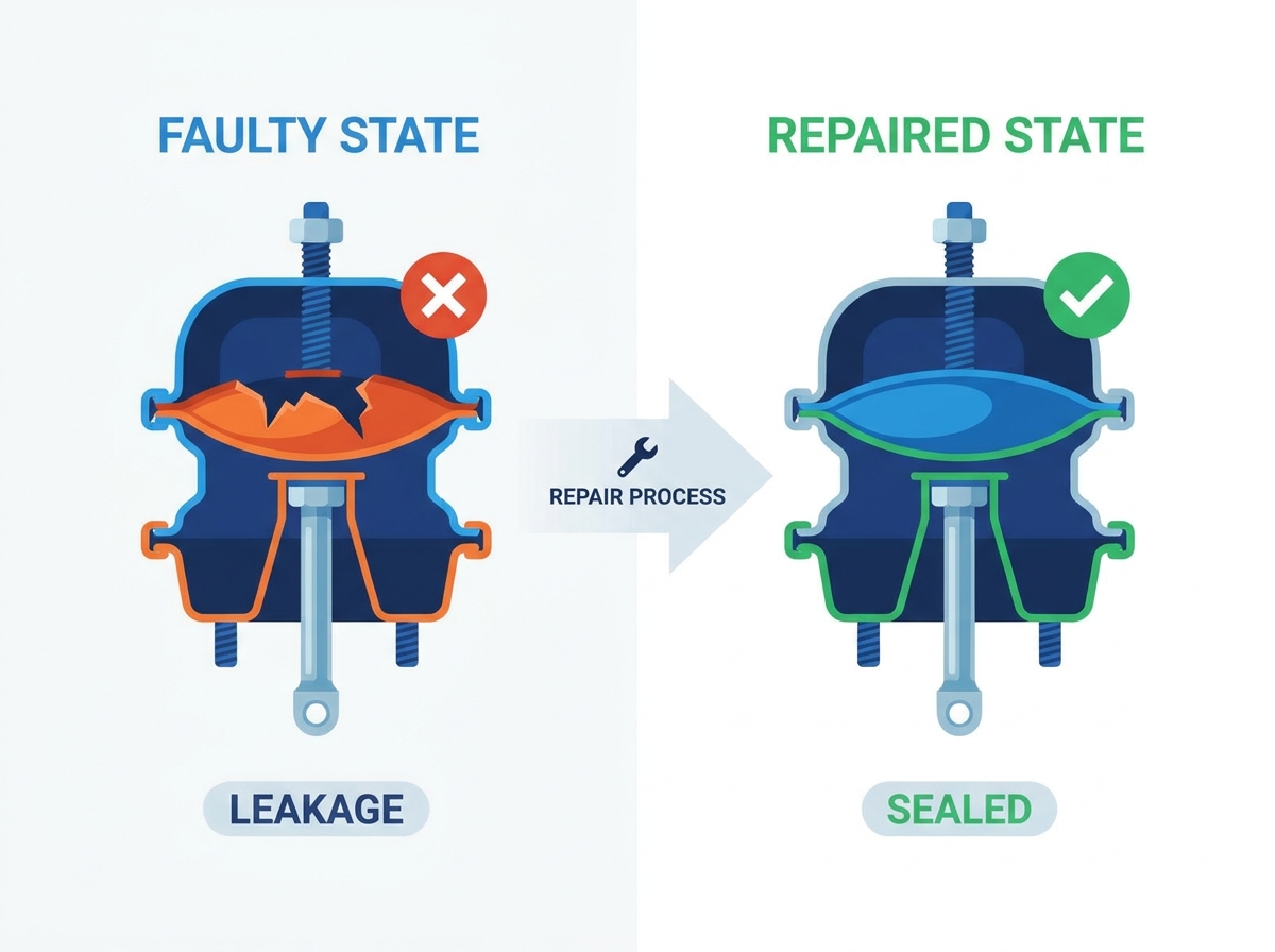
Before putting a wrench to heavy machinery, you must understand the structural components of the pneumatic system. A commercial air brake chamber is a highly engineered mechanical device. It converts compressed air pressure into the raw mechanical force required to halt a heavy-duty vehicle. Identifying the two primary sections of a standard tandem assembly is your starting point.
Heavy-duty trucks utilize a dual-chamber system on the rear drive and trailer axles. Industry veterans commonly refer to this as a tandem or piggyback chamber.
The Service Chamber: Situated closest to the slack adjuster. This front section applies normal stopping force when the driver depresses the foot valve. Compressed air rushes into this housing and expands a flexible rubber diaphragm. This expansion pushes a metal rod outward to mechanically engage the foundation brakes.
The Spring Chamber: Bolted to the rear of the assembly. This sealed unit acts as the parking and emergency brake. In contrast to the service side, the spring chamber relies on a heavy-duty mechanical coil to force the brakes closed. Pneumatic pressure is required to compress this spring and allow the wheels to turn freely.
When compressed air enters the service port, it forcefully pushes against the heavy-duty rubber diaphragm. This diaphragm forces a steel pushrod outward. The pushrod connects to a slack adjuster via a clevis pin. Its extension rotates the adjuster. This rotational movement turns the S-cam. The brake shoes spread apart and force themselves against the spinning brake drum to create stopping friction.
Chamber Section | Primary Function | Actuation Method | Repairability |
|---|---|---|---|
Service Chamber | Standard braking during driving | Compressed air pushes diaphragm | Diaphragm can be replaced safely |
Spring Chamber | Parking and emergency braking | Mechanical spring force | Do NOT open. Replace entire unit |
Accurate diagnostics prevent the unnecessary replacement of perfectly good components. A failing unit exhibits specific observational and operational symptoms. Recognizing these warning signs early is critical for maintaining fleet safety and avoiding costly roadside out-of-service violations.
The most frequent indicator of a failing system is an audible air leak. The internal rubber diaphragm develops a tear due to age, extreme temperature fluctuations, or continuous internal friction. Compressed air escapes into the atmosphere. You will hear a distinct hissing sound coming from the wheel well when the brake pedal is applied. This indicates a service diaphragm leak. A hiss when the dash valve is pushed in indicates a spring chamber seal failure.
A compromised pneumatic chamber cannot deliver optimal mechanical force to the slack adjuster. If a diaphragm is leaking, that specific wheel end will not receive full stopping power. Operationally, the steering wheel pulls hard to one side during a sudden stop. The foot pedal feels distinctly spongy. The vehicle experiences a measurable and dangerous increase in total stopping distance.
Visual inspections during a standard pre-trip walkaround often reveal structural failures. Look closely at the exterior steel housing. Dented casings internally bind the diaphragm or the power spring. Missing or heavily corroded clamp bands completely compromise the airtight seal. Noticing these issues requires immediate action. Consulting a heavy-duty parts specialist is the best course of action to secure replacement hardware before a catastrophic blowout occurs.
Heavy-duty truck maintenance requires strict adherence to safety protocols. Understanding the inherent physical risks is vastly more important than mastering the mechanical repair itself.
A standard Type 30/30 unit contains a heavy-duty steel power spring housed in the rear section. The factory permanently compresses this specific coil with up to 2,500 pounds of raw kinetic force. You must never attempt to remove the clamp band securing the spring brake housing. If this tamper-resistant clamp is cut, the metal housing will explode outward with lethal velocity. The spring side is a permanently sealed unit. If it fails, discard and replace the entire assembly.
Establish a highly secure working environment before touching a single wrench.
Maneuver your rig onto a level, reinforced concrete pad. Avoid gravel or soft dirt where floor jacks and chocks might sink. Securely wedge heavy-duty rubber wheel chocks tightly behind and in front of the tires on axles not being serviced. Open the petcocks to deplete all compressed air from the primary and secondary air tanks. Listen to the hiss of the draining tanks. This ensures the system cannot accidentally actuate while your hands are near dangerous pinch points. Always utilize ANSI-approved safety glasses and wear heavy-duty mechanic gloves.
Efficiency in the shop depends heavily on utilizing the correct tools. Attempting to service commercial air systems with improvised equipment leads to stripped brass fittings, compromised rubber seals, or severe physical injury.
The caging bolt is a specialized threaded rod featuring a T-shaped head. It is conveniently stored in a dedicated molded slot on the side of the chamber itself. This specific tool is absolutely necessary to manually draw back and lock the dangerous parking spring before any disassembly begins.
You need a robust set of hand tools designed specifically for the rigors of commercial vehicle maintenance.
Tool Category | Specific Item | Application in Repair |
|---|---|---|
Wrenches | Line wrenches | Safely removing soft brass air line fittings without stripping the hex heads. |
Sockets | Deep socket set and heavy-duty ratchet | Removing rusted clamp band nuts and torqueing the caging bolt nut. |
Pliers | Heavy-duty locking pliers | Extracting the stubborn cotter pin from the clevis linkage assembly. |
Impact Tools | Dead-blow hammer | Gently tapping and separating heavily rusted chamber halves without denting the aluminum. |
Depending on your diagnostic findings, prepare specific replacement components on your workbench. Procure an OEM-spec replacement rubber diaphragm of the correct size. If replacing the unit entirely, you need a complete piggyback kit or a full brake chamber assembly. Ensure you have fresh O-rings and high-quality liquid thread sealant for the pneumatic fittings.
This methodical procedure outlines replacing a ruptured service diaphragm. This workflow assumes the rear spring brake section remains structurally intact and fully functional.
Properly chock the wheels and completely drain the air tanks. You must manually cage the power spring. Remove the rubber dust cap from the center access hole at the rear of the spring housing. Extract the caging T-bolt from its storage pocket. Insert the T-bolt straight into the rear hole until it bottoms out against the internal pressure plate. Twist the bolt a quarter-turn to securely lock the T-head. Place the heavy washer and nut onto the threaded end. Tighten the nut using a deep socket and ratchet. You will feel the mechanical resistance as you manually draw the spring back.
Use a piece of masking tape to clearly label the primary and secondary air lines to avoid pneumatic confusion later. Carefully break loose and remove the air line fittings from the service ports using a properly sized line wrench. Locate the clevis assembly connecting the steel pushrod to the slack adjuster. Bend and remove the cotter pin. Slide the metal clevis pin out of the joint. The pushrod is now completely isolated.
Locate the two-piece metal clamp band holding the front and rear halves of the service chamber together. Slowly loosen the retaining nuts using a socket wrench. Slight residual tension may be trapped inside even with the air fully drained. Loosen the nuts evenly. Remove the clamp entirely once it is loose enough. Carefully pull the front housing away from the heavy rear assembly.
Pry away the old rubber diaphragm. Take note of brittle edges or deep abrasions that hint at internal friction. Inspect the inside of the aluminum housing for deep pitting, excessive rust scale, or foreign debris. Thoroughly clean the seating rim with a stiff wire brush and a rag soaked in parts cleaner. Dirt or rust left on this lip will inevitably cause a new air leak. Place the fresh diaphragm perfectly flat against the housing. Ensure the molded lip seats precisely into the designated circular groove.
Carefully align the front housing back over the new diaphragm. Ensure the bolt holes and pushrod orientation match the slack adjuster geometry. Reinstall the metal service clamp band over the joined halves. Tighten the clamp nuts evenly to ensure uniform pinching pressure across the rubber seal. Reconnect the pushrod to the slack adjuster using the clevis pin. Secure it safely with a brand-new cotter pin. Reattach the labeled air lines to their respective ports. Ensure the brass threads are clean and properly treated with thread sealant.
Mastering how to swap out a service diaphragm is a highly valuable skill. However, it is not always the most practical or safe solution. Fleet managers must critically evaluate when a simple patch job is insufficient.
Diagnostic testing might reveal that the hissing air leak originates from the sealed spring brake section. The rear housing might be visibly dented, heavily rusted, or structurally compromised. This section cannot be repaired. The internal spring mechanism is permanently sealed at the factory for a reason. In this severe scenario, discard and replace the entire piggyback unit or the complete assembly.
The commercial vehicle maintenance industry has seen a massive shift toward full piggyback replacements. Rising labor rates and stringent liabilities associated with fleet safety drive this change. Modern fleets mandate replacing the entire unit rather than risking a secondary failure from a rebuilt housing. The labor time required to disassemble, wire-brush, rebuild, and test a heavily rusted chamber vastly exceeds the cost of a brand-new unit. Swapping the entire assembly is frequently faster and inherently safer. Sourcing a complete brake chamber assembly through certified professionals yields a much more reliable long-term result.
How do you choose the right replacement? You must look closely at the engineering specifications. High-quality chambers feature heavy-duty 8-gauge steel housings and epoxy-coated power springs to resist severe corrosion.
Standard stroke Type 30/30 chambers offer a 2.0-inch maximum stroke. Long stroke versions provide a 2.5-inch or 3.0-inch stroke for enhanced braking reserve. Ensure the service and emergency ports match your existing plumbing. These are typically 3/8-inch NPTF ports. Standard pushrods use 5/8-11 UNC threads. Premium units are hydrostatically tested to withstand up to 150 PSI maximum operating pressure. Consulting a reliable brake chamber manufacturer guarantees exact OEM fitment for heavy-duty applications.
Successfully replacing the rubber diaphragm is only the first phase of the maintenance process. The vehicle is still not ready for active highway operation. Rigorous post-repair testing and precise mechanical adjustments are absolutely mandatory.
Safely release the mechanical tension secured prior to the repair. Start the truck engine and allow the air compressor to build system pressure to the standard operating range. Press the yellow dash valve to supply air to the parking brakes once fully pressurized. This pneumatic pressure compresses the internal power spring and relieves the physical tension on your manual caging T-bolt.
Carefully loosen the nut on the caging bolt. Push the bolt in slightly, twist it a quarter-turn to unlock it, and slide it out of the housing. Perform a comprehensive leak test using a specialized leak-detection solution or a thick mixture of dish soap and water. Spray the soapy solution generously over the service clamp band, all threaded air line fittings, and the pushrod exit hole. Have an assistant firmly apply the service brake pedal while you observe the treated areas. Active, expanding bubbles indicate escaping air.
Inspection Area | Observation | Possible Cause | Required Action |
|---|---|---|---|
Service Clamp Band | Rapid, continuous bubbling | Misaligned diaphragm or loose clamp band | Depressurize system, realign the rubber diaphragm, and re-torque the clamp band evenly. |
Air Line Fittings | Small, foaming bubbles | Degraded thread sealant or loose fitting | Tighten the fitting slightly. Replace the thread sealant if leaking persists. |
Pushrod Hole | Hissing sound with bubbles | Internal pushrod seal failure or ruptured diaphragm | The internal seal is compromised. Fully replace the brake chamber or piggyback unit. |
Spring Housing | Bubbles from the sealed clamp | Cracked housing or failed internal spring seal | DANGER: Do not attempt repair. Replace the entire sealed spring brake chamber immediately. |
Precise foundation brake calibration is more critical than ever due to collision mitigation technology in modern fleets. These computer-controlled systems rely on instantaneous mechanical response. A slack adjuster slightly out of specification drastically impairs an automated emergency braking event.
Measure the applied stroke after repairing a brake chamber. Build the air pressure to 100 psi, turn off the engine, chock the wheels, and release the parking brakes. Measure the distance from the face of the chamber to the center of the clevis pin. Have an assistant fully apply the brake pedal and take a second measurement. The difference between these two numbers is your applied brake stroke.
Chamber Type | Outside Diameter | Maximum Legal Stroke Limit |
|---|---|---|
Type 20 | 6 - 23/32 inches | 1 - 3/4 inches |
Type 24 | 7 - 7/32 inches | 1 - 3/4 inches |
Type 30 | 8 - 3/32 inches | 2 inches |
Type 30 (Long Stroke) | 8 - 3/32 inches | 2 - 1/2 inches |
The slack adjuster must be addressed if the measured stroke exceeds legal limits. Turn the adjusting mechanism on manual slack adjusters until the brake shoes contact the drum. Back it off approximately one-half turn. Do not manually adjust Automatic Slack Adjusters to compensate for excessive stroke. These are designed to self-adjust. The internal ratcheting mechanism is likely broken and requires replacement if they fail to do so.
Maintaining the air brake system on a heavy-duty commercial vehicle is a highly complex responsibility. Replacing a service diaphragm leaves zero margin for error. The immense kinetic energy stored within the power spring demands strict legal compliance.
An improperly repaired unit leads to disastrous consequences. The metal housing becomes a lethal projectile if a clamp band fails under pressure. Prioritizing safety and professional expertise is always the most prudent business decision. Experiencing persistent air leaks? Dealing with a heavily corroded undercarriage? You should contact heavy-duty parts experts for immediate assistance.
Partnering with knowledgeable specialists ensures your vehicle runs OEM-quality components engineered to withstand brutal commercial freight conditions. Technical support keeps your assets compliant and your drivers safe.
Repairing a brake chamber demands a methodical approach and strict adherence to safety protocols. Mechanics must thoroughly understand the functional differences between the service and spring components before turning a wrench. Always cage the power spring safely. Meticulously clean sealing surfaces. Conduct rigorous post-repair leak testing. This guarantees your heavy-duty truck remains completely safe for highway operation. Maintaining optimal air brakes protects your cargo and everyone sharing the road. Never compromise on your vehicle maintenance standards. Ready to upgrade your pneumatic system? Explore premium replacement parts from the AHEM Group product catalog today.
No. You must never attempt to repair or open the spring brake side of a brake chamber. The parking brake section contains a heavy-duty steel power spring mechanically compressed with up to 2,500 pounds of force. This section is permanently sealed at the factory using a tamper-resistant metal band. Attempting to cut or pry this band releases immense kinetic energy instantaneously. This explosive release launches the heavy metal housing outward at lethal velocities. Discard and replace the entire sealed piggyback unit or the complete brake chamber assembly if the spring section is leaking air or structurally damaged.
Changing a standard Type 30/30 brake chamber generally takes between 30 to 60 minutes per wheel end for a trained diesel mechanic. This timeframe is highly dependent on the environmental condition of the vehicle. Heavy-duty trucks subjected to road salt and severe weather suffer from extreme undercarriage corrosion. The mounting nuts securing the chamber to the axle bracket become heavily rusted and seized. The clevis pin connecting the pushrod to the slack adjuster often seizes inside the linkage. Technicians spend additional time applying penetrating fluids, using heavy-duty impact wrenches, or utilizing an induction heater to free seized components in these scenarios.
The consequences depend entirely on which side of the brake chamber is compromised. Commercial vehicles utilize a dual-circuit air brake system designed with built-in redundancies. You instantly lose all service braking power on that specific wheel if the rubber diaphragm on the service side blows out while driving. You will hear a massive air leak when you press the brake pedal. The air compressor struggles to keep up with rapid air loss. The low-air warning buzzer and dashboard light activate if system pressure drops below 60 psi. The tractor protection valve activates if pressure plummets to 20 to 45 psi. This removes air from the spring chambers and causes the heavy emergency power springs to automatically deploy. The heavy vehicle comes to an abrupt, uncontrollable stop.
A compromised service diaphragm presents distinct operational symptoms. The most obvious indicator is a loud, aggressive hissing sound coming from the wheel area whenever the service brake pedal is applied. Pressurized air bypasses the seal and exhausts directly into the atmosphere instead of pushing the mechanical rod. The driver experiences a spongy or unresponsive brake pedal feel. The truck pulls sharply to the left or the right during hard braking events because the affected wheel provides no stopping friction. The air compressor cycles on much more frequently than normal to replenish air tanks drained by the continuous leak.
Standard stroke chambers typically offer a 2.0-inch maximum stroke limit before the pushrod bottoms out. Long stroke chambers provide up to 2.5 or 3.0 inches of stroke. This extra travel provides a significantly greater braking reserve. It compensates for brake drum expansion that occurs during heavy, high-heat braking events on steep downgrades. Long stroke chambers are easily identified by square air ports or a special trapezoidal tag attached to the clamp band.
Chock the wheels and build system air pressure to 120 psi. Release the parking brakes. Apply a thick soapy water solution around the pushrod exit hole on the service chamber housing. Have an assistant firmly press and hold the service brake pedal. Observe the pushrod hole closely. If bubbles form rapidly around the pushrod, the internal center seal between the spring and service sections has failed. Pressurized air is bleeding across the chambers. The entire unit must be replaced immediately.
