
Views: 0 Author: Site Editor Publish Time: 2026-10-31 Origin: Site


You hear that faint hiss echoing under the chassis. You trace the sound to a relay valve and confidently swap it out. You air the truck back up, only to realize the hiss is still there. Sound familiar? This is a classic trap for heavy-duty mechanics. Pinpointing pneumatic leaks often feels like chasing a ghost. One of the most common, yet frequently misdiagnosed issues is a back feeding brake chamber. When the internal rubber seals degrade, pressurized air from the parking brake circuit bleeds directly into the service brake section.
This internal failure triggers a cascade of shop headaches. You face continuous air loss, an overworked compressor running dangerously hot, and severe safety hazards on the highway. Because this rogue air travels backward up the service lines and exhausts out of a relay valve, technicians routinely mistake the symptom for the root cause. This comprehensive diagnostic guide breaks down the fluid dynamics behind back feeding. We will outline the non-negotiable safety protocols and detail a highly effective process to isolate the true culprit. This methodical approach ensures you get the rig back on the road safely and efficiently.
The Core Mechanism: Back feeding occurs when the internal center seal, which is usually a heavy-duty O-ring, ruptures. This allows high-pressure air to cross from the parking side into the service side.
Safety First: Releasing the parking brakes is mandatory for this diagnostic test. Consequently, you must chock the wheels securely to prevent catastrophic roll-aways.
The Diagnostic Strategy: You can definitively identify a compromised chamber by pressurizing the spring brakes, removing the service air line, and physically feeling for air escaping from the open service port.
The Resolution: These sealed units cannot be rebuilt internally due to lethal spring tension. The piggyback section or the complete assembly must be swapped out for a compliant replacement.
To accurately troubleshoot back feeding, you first need to visualize the internal anatomy of a dual-chamber system. In the commercial transport world, this component is widely recognized as a spring brake chamber. It functions essentially as two separate actuators bolted together. They work in tandem to manage standard braking and emergency parking.
Positioned at the front of the assembly, this section sits closest to the pushrod and slack adjuster. It remains completely dormant until the driver steps on the foot pedal. Specifically, regulated air rushes down the line, filling this forward cavity and pushing against a flexible rubber diaphragm. This mechanical action violently thrusts the pushrod outward. This applies the foundation brakes to decelerate the massive vehicle.
In contrast, the rear housing contains a massive, tightly coiled mechanical steel spring. The operation here is inverse. When system pressure is dumped, such as when you pull the yellow dash valve, the spring violently expands to mechanically lock the wheels. To move the truck, you must supply 100 to 120 PSI of air into this chamber. This physically compresses the spring and releases the brakes.
Separating these two distinct pressure zones is a robust center seal. Its sole purpose is to isolate the constant, high-pressure air holding the mechanical spring back. As long as this seal remains intact, the adjacent service chamber stays perfectly empty during normal cruising.
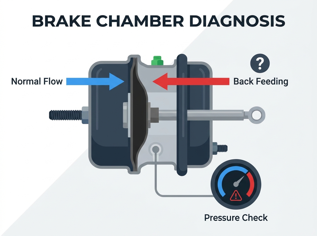
The phrase is thrown around in maintenance bays constantly. However, understanding the precise fluid dynamics behind it is crucial for accurate diagnostics.
Back feeding initiates the moment that vital center seal tears or degrades. The high-pressure air, which is actively working to keep the parking spring compressed, sneaks past the broken barrier. It continuously bleeds into the service brake chamber, creating an unwanted pneumatic imbalance.
Because the service brake line is unpressurized when the driver removes their foot from the pedal, the leaking air seeks the path of least resistance. It travels backward up the service line. Eventually, this rogue air reaches the nearest relay valve or quick release valve. It continuously hisses out of the exhaust port. This specific symptom is exactly what tricks mechanics into replacing a functional valve. They entirely miss the back feeding brake chamber hidden further down the axle.
Crawling under a heavy-duty chassis to manipulate air systems is inherently dangerous. The sheer mechanical force and sudden blasts of compressed air can cause severe injuries. Never bypass these mandatory safety protocols.
This diagnostic procedure requires you to release the parking brakes while positioned underneath the rig. Consequently, the truck will have zero mechanical holding force. You must aggressively wedge heavy-duty, DOT-approved wheel chocks in front of and behind multiple tires. Verify the vehicle is parked on dead-level concrete before beginning.
Personal Protective Equipment is non-negotiable. Wear impact-resistant safety glasses at all times. When you crack open an air line, trapped pressure can launch rust flakes and road grime directly into your eyes. Furthermore, thick mechanic gloves will save your knuckles from sharp chassis components.
Under no circumstances should you attempt to cut, torch, or unbolt the sealed rear housing of a spring brake. The kinetic energy stored in that coiled steel is lethal. Modern units are permanently crimped at the factory specifically to prevent technicians from accidentally deploying the spring.
Methodical isolation is the only way to avoid parts-cannon diagnostics. Follow this objective sequence to find the exact source of your air loss.
Climb into the cab and fire up the diesel engine. Let the air compressor run until it hits the governor cut-out point. This is typically between 120 and 130 PSI. You will know it is ready when you hear that familiar, sharp purge from the air dryer. Once fully pressurized, shut the engine down completely. A dead-quiet shop environment is essential for hearing faint pneumatic leaks.
Push in the yellow or red parking brake knob on the dashboard. This action sends system air rushing into the spring brake chambers, compressing the mechanical springs. Double-check your wheel chocks one last time, as the vehicle is now free-rolling.
Slide under the axle and locate the suspect brake chamber. Grab your wrench and carefully loosen the fitting on the service port. Remember, the service port is always the one positioned closest to the pushrod. Carefully pull the rubber hose away from the fitting.
With the parking brakes still released, place your bare finger or the palm of your hand flush against the open service port on the chamber itself. Focus on any sensation of air pushing against your skin.
Once you have the line removed, the direction of the escaping air tells you exactly which component has failed. Sourcing reliable replacement brake parts becomes much easier when you know exactly what is broken.
If you feel a steady, continuous stream of air blowing outward from the metal port of the chamber, the internal center seal is officially blown. High-pressure air from the parking side is bypassing the seal. You have successfully confirmed a back feeding brake chamber.
In contrast, if the chamber port is dead silent, but air is violently hissing out of the rubber hose you just disconnected, the chamber is perfectly fine. This symptom points upstream. You are likely dealing with a faulty relay valve, a damaged tractor protection valve, or a failing anti-compounding valve.
If neither the port nor the hose exhibits any air movement, this specific wheel end is functioning properly. Thread the service line back on, tighten it securely, and slide over to test the next chamber on the axle.
In recent years, the commercial trucking sector has witnessed a significant shift toward predictive maintenance and enhanced pneumatic diagnostics. Fleet managers are acutely aware that misdiagnosing back-feeding issues inflates operational downtime. As modern pneumatic systems operate at higher, more demanding pressures to meet stringent stopping distance regulations, the stress placed on internal rubber seals has intensified. Consequently, there is a growing industry demand for robust components engineered with advanced synthetic elastomers. These newer materials are specifically designed to withstand extreme thermal cycling and resist the degrading effects of oil blow-by. This technological shift ultimately extends the service intervals of heavy-duty fleets and reduces unexpected compliance violations.
Understanding the root causes of seal degradation helps fleets implement smarter preventative maintenance schedules.
The center seal is a dynamic, moving part. It shifts minutely every single time the driver taps the brakes. Over hundreds of thousands of highway miles, this constant mechanical friction naturally thins the rubber. Eventually, it simply lacks the material density to hold back 120 PSI of constant pressure.
Dirty air is the number one killer of pneumatic valves. If an aging air compressor allows hot engine oil to bypass its piston rings, that sludge travels directly into the air tanks. Mixed with condensation, this toxic emulsion reaches the brake chambers. It causes the rubber seals to swell, soften, and disintegrate prematurely.
Commercial trucks operate in unforgiving environments. Plunging winter temperatures cause rubber seals to shrink and harden. This prevents them from seating flush against the metal housing. Conversely, radiant heat from heavy downhill braking bakes the rubber, completely destroying its elasticity.
Once you have isolated a back feeding issue, internal repair is off the table. It is strictly a replacement job.
Because the spring housing is factory-sealed to prevent fatal accidents, you cannot crack it open to swap a cheap internal seal. You must replace either the piggyback section or the entire assembly. Industry veterans highly recommend replacing the complete unit. If the center seal has failed from old age, the front service diaphragm is likely on the verge of tearing as well.
Never gamble with bargain-bin braking components. Using inferior parts often leads to uneven braking force, rapid seal failure, and DOT out-of-service violations. Always source premium components engineered for extreme conditions. For instance, top-tier commercial vehicle brake components are built to handle a rated working pressure of 800Kpa and a maximum working pressure of 1Mpa. They are designed to operate flawlessly in ambient temperatures ranging from negative 40 degrees Celsius up to positive 80 degrees Celsius. By choosing parts with a life expectancy exceeding one million cycles, you guarantee precise stroke lengths and rigorous regulatory compliance.
Specification | Standard Brake Chamber | Premium Engineered Chamber |
|---|---|---|
Working Pressure Capability | Up to 120 PSI | Rated 800Kpa / Max 1Mpa |
Operating Temperature Range | -20°C to +60°C | -40°C to +80°C |
Cycle Life Expectancy | Approx. 500,000 cycles | ≥ 1,000,000 cycles |
Internal Seal Material | Standard Nitrile Rubber | Advanced Synthetic Elastomers |
The most cost-effective strategy for handling back feeding is preventing it entirely. Keeping the air system clean exponentially extends the life of every valve on the chassis.
Your air tanks act as reservoirs for the entire braking network. Drain the primary and secondary tanks daily using the manual lanyards. If your rig utilizes automatic drain valves, physically inspect them to ensure they are actually spitting out moisture. Evacuating water and oil sludge is your absolute best defense against seal degradation.
The air dryer is the ultimate gatekeeper. You should swap out the desiccant cartridge annually, or more frequently if you run in humid coastal climates. A healthy dryer strips moisture and oil aerosols before they ever reach the tanks. When upgrading your filtration, investing in heavy-duty air brake products ensures your downstream components remain pristine.
Incorporate a quiet listening period into your daily post-trip walkaround. After chocking the wheels and releasing the parking brakes with the engine off, walk slowly past each axle. Catching a faint hiss in the terminal yard allows you to schedule a controlled repair. This prevents suffering an emergency breakdown on the interstate.
Mastering this diagnostic procedure is an indispensable skill for heavy-duty technicians and proactive owner-operators. By recognizing that a ruptured center seal forces parking air into the service side, you can eliminate the frustrating cycle of replacing the wrong parts. Always prioritize safety by chocking the wheels. Rely on the methodical hose-removal test to isolate the leak, and immediately swap defective units with premium replacements. A rigorously maintained, leak-free air brake system is the foundation of a safe and highly profitable commercial vehicle. If you are looking to upgrade your fleet's stopping reliability, explore the engineered solutions at Ahem Group to find the exact, high-cycle brake components your heavy-duty applications demand.
Absolutely not. A back feeding chamber constitutes a continuous, severe air leak. This represents a critical failure in the commercial pneumatic system. This defect drastically compromises stopping reliability and is a direct violation of DOT safety regulations. The truck must be placed out of service immediately until the chamber is replaced.
While instinct might suggest the relay valve itself is defective, it is incredibly common for a back feeding brake chamber to cause this exact symptom. The high-pressure air bypasses the broken internal seal, travels backward up the empty service line, and ultimately vents out of the relay valve's exhaust port. Always test the brake chambers first to avoid unnecessary valve replacements.
No. Modern spring brake chambers are engineered to be tamper-proof and are permanently sealed at the manufacturing facility. The internal mechanical spring is caged under thousands of pounds of lethal pressure. If the center seal fails, you must replace the entire spring brake section or the complete brake chamber assembly to ensure safety.
The operational lifespan of a brake chamber depends heavily on driving conditions, regional climates, and the rigor of your preventative maintenance program. On average, a standard unit will perform for 3 to 5 years. However, premium engineered chambers can easily exceed one million cycles, provided the internal air supply is kept strictly free of oil blow-by and moisture.
You need very minimal equipment for this straightforward diagnostic procedure. Gather heavy-duty wheel chocks to secure the chassis, safety glasses and gloves for personal protection, and a standard open-end wrench to safely crack open and disconnect the service air line from the chamber port.
To manually release a spring brake chamber when system air pressure is lost, you must cage the brake. This involves removing the caging bolt from its storage pocket on the side of the chamber. You insert it into the rear housing, twist it to lock it into the internal pressure plate, and tighten the nut with a wrench. This mechanical action compresses the heavy steel spring, freeing the foundation brake so the vehicle can be safely towed.
The numbers refer to the effective square inch area of the internal rubber diaphragms. A Type thirty-thirty brake chamber has thirty square inches of surface area for both the service brake and the spring brake sections. This makes it standard for heavy-duty drive and trailer axles. A Type twenty-twenty-four has twenty square inches for the service side and twenty-four for the parking side. These are typically used on lighter axles or steer axles where less braking force is required.
