
Views: 0 Author: Site Editor Publish Time: 2026-10-08 Origin: Site


Air brake systems serve as the backbone of commercial vehicle safety. When a fully loaded semi-truck navigates a steep highway grade, reliable stopping power is absolutely critical. A failing pneumatic system presents a massive hazard to the operator and the public. Furthermore, it triggers immediate out-of-service violations during Department of Transportation roadside inspections.
The brake chamber acts as the mechanical heart of this network. It converts compressed air into the physical force required to press brake shoes against drums. Extreme pressure and harsh environments inevitably degrade internal components. Rubber diaphragms tear. Heavy-duty springs suffer metal fatigue. Exterior steel housings corrode. Ultimately, component replacement becomes unavoidable.
Replacing a spring brake actuator involves significant operational risk. You are dealing with a highly compressed internal power spring. Mishandling this spring can release explosive, lethal force. This guide walks you through executing this repair safely and efficiently. Sourcing premium replacement parts from an experienced commercial vehicle components manufacturer ensures your fleet maintains optimal stopping power.
Safety is Non-Negotiable: You must properly chock the vehicle wheels, completely drain the air system, and mechanically cage the power spring before attempting any disassembly.
Identify the Failure: Learn to accurately spot the signs of a bad braking unit, such as audible hissing air leaks, sluggish response, or a truck pulling sharply to one side.
Precision Matters: Measuring and cutting the pushrod on the new actuator to match the exact length of the old one is critical for proper calibration and compliance.
Quality Parts Save Money: Investing in a premium replacement prevents premature mechanical failures and significantly reduces costly vehicle downtime.
Recent transportation analytics reveal a massive shift in fleet maintenance strategies. Regulatory bodies like the Commercial Vehicle Safety Alliance are intensifying their focus on brake stroke compliance. During recent enforcement blitzes, brake system violations accounted for the highest percentage of out-of-service orders. Consequently, modern fleet managers are abandoning reactive repairs. They are adopting proactive, data-driven maintenance schedules.
The industry is also seeing a surge in demand for corrosion-resistant housings and extended-life diaphragms. Fleets realize that a single roadside violation costs exponentially more than upgrading to premium pneumatic components. Maintaining peak mechanical integrity is no longer just about passing inspections; it is a core component of profitable fleet operations.
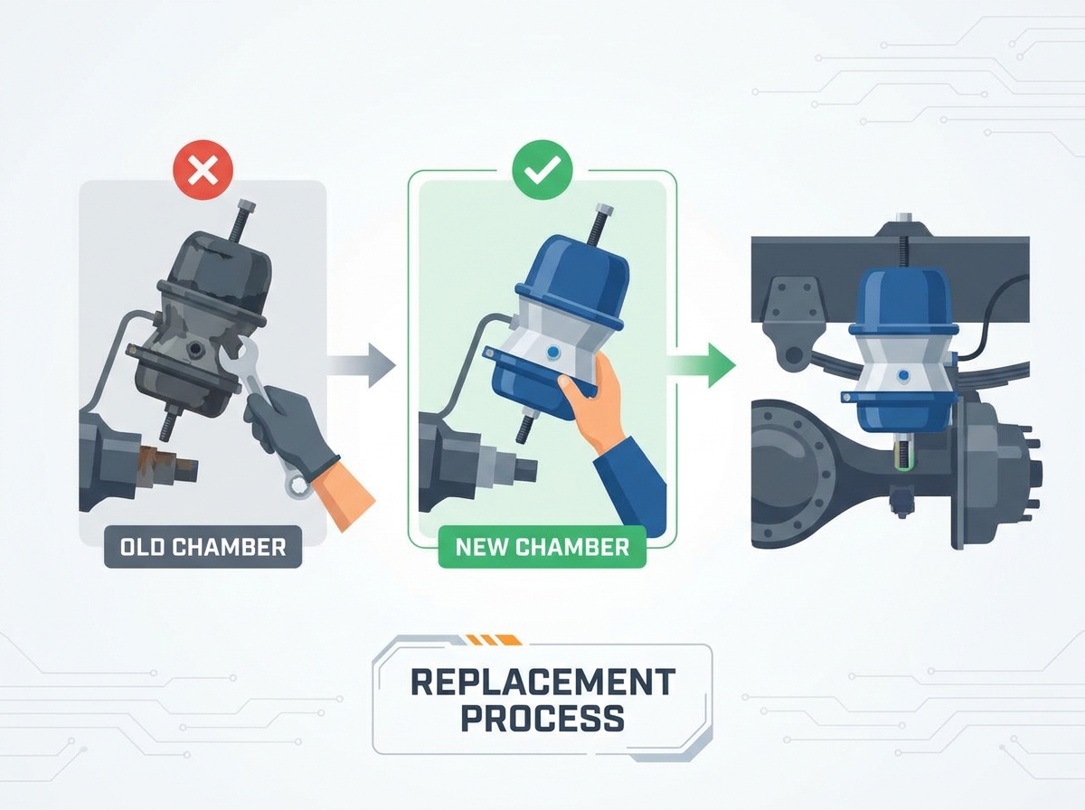
To maintain a commercial chassis properly, you must understand its mechanical functions. A pneumatic actuator is a steel container located at each wheel end. It translates air pressure into mechanical pushrod force. This force rotates the slack adjuster and S-cam to apply friction to the drums.
There are two primary types to monitor. A standard service chamber handles everyday braking while in motion. In contrast, a dual-chamber spring brake contains both a service section and a secondary parking section housing a massive coil spring.
Recognizing early warning signs prevents dangerous roadside breakdowns. The most frequent failure is a ruptured internal rubber diaphragm. Compressed air escapes the closed loop. This presents as a distinct hissing sound when the pedal is pressed. Specifically, a failing unit will not apply the same mechanical force as others on the axle. The heavy-duty vehicle will pull sharply to one side during braking events. Deep rust scaling or heavy dents on the outer metal housing compromise structural integrity. A bent pushrod requires immediate attention. A brake stroke extending beyond the legal adjustment limit guarantees a failed inspection. A weak internal return spring prevents the pushrod from retracting fully.
Safety remains the absolute primary focus when working on heavy-duty pneumatic systems. The parking section of a dual-chamber unit contains a heavy-duty coil spring held under thousands of pounds of compressive force. Never attempt to loosen or cut the metal clamp ring securing the rear spring housing. Opening this housing without specialized factory containment equipment causes fatal outward explosions.
Before touching the chassis, immobilize the vehicle completely. Park the truck and trailer on a solid, level concrete surface. You will be releasing the parking brakes and draining the air system. The vehicle will possess zero mechanical holding power. Heavy-duty wheel chocks on both the front and rear tires are mandatory.
Working on pressurized air lines is extremely dangerous. Ensure absolutely zero air pressure remains in the lines before disconnecting pneumatic fittings. Open the petcock drain valves located on the bottom of the primary and secondary air tanks. Alternatively, pump the foot brake pedal repeatedly with the engine off until dashboard gauges read zero. Disconnecting a pressurized hose causes it to whip violently.
Having the correct tools prepared streamlines the maintenance process and reduces frustration. The caging bolt and nut are the most critical tools. They are often included with a new unit or stored in a slot on the side of the existing housing. Heavy-duty wrenches remove mounting hardware. Pliers and wire cutters are necessary for extracting cotter pins. New assemblies feature an extended universal pushrod. You must measure and cut it precisely using a measuring tape and angle grinder. Liquid thread sealant prevents future pressure leaks at brass fittings.
Verify you have the exact size and type of replacement unit. The industry standard for heavy-duty drive axles is a Type 30/30. When sourcing these critical safety components, choosing a reputable air brake system supplier is paramount. For instance, high-grade units feature 8-gauge steel housings treated with advanced e-coating for superior rust prevention. Their internal diaphragms utilize ozone-resistant synthetic rubber engineered to withstand over one million compression cycles.
Investing in quality parts directly impacts your bottom line. Here is a breakdown of why premium actuators outperform cheap alternatives.
Feature | Premium Manufacturer Standards | Economy Aftermarket Parts |
|---|---|---|
Housing Material | Heavy-duty 8-gauge steel with e-coating | Thin stamped steel, prone to rapid rust |
Diaphragm Quality | Ozone-resistant synthetic rubber blend | Standard rubber, tears under extreme cold |
Power Spring | Epoxy-coated, heat-treated steel | Untreated metal, high risk of fatigue failure |
Cycle Life | Tested to exceed 1,000,000 cycles | Often fails before 300,000 cycles |
Pressure Rating | Safely operates up to 800 kPa | Prone to deformation under high pressure |
Caging mechanically compresses and locks the internal parking brake spring. This safely retracts the pushrod and removes tension from the slack adjuster. The unit becomes safe to unbolt.
Locate the access hole on the flat back side of the housing. Scrape away accumulated road grime to clearly see the receptacle slot. Remove the rubber dust cap. Insert the T-shaped caging bolt straight into the hole. Push it firmly through the internal plate. Once it bottoms out, twist the bolt exactly one quarter-turn to lock the T-head securely into place.
Slide the heavy flat washer over the threaded end, followed by the nut. Use a hand wrench to tighten the nut down against the metal housing. Turning the nut clockwise slowly pulls the bolt outward, compressing the heavy internal spring. Continue tightening until the pushrod is fully retracted. Do not use an impact gun. Excessive torque strips the threads or damages the internal pressure plate.
With the internal spring safely caged and the pneumatic system completely drained, initiate the physical removal.
Double-check your dashboard gauges to ensure the air system is empty. Locate the two air lines connected to the side of the cylinder. Carefully unscrew the service and emergency air line fittings. Mark these lines with colored tape to ensure correct reconnection later. Reversing these lines causes the entire braking system to malfunction.
The pushrod connects to the slack adjuster via a metal U-shaped clevis and a thick steel clevis pin. Straighten and extract the cotter pin securing the assembly. Slide the smooth clevis pin free. If the pin is seized from winter salt exposure, apply penetrating oil and tap it lightly with a hammer.
The unit is secured to a heavy steel bracket on the axle by two large mounting studs. Remove the two large mounting nuts and their corresponding washers. The assembly is quite heavy. Support the weight of the unit with one hand as you remove the final nut. Carefully pull the heavy cylinder straight back and away from the mounting bracket.
Preparation dictates the success of the installation. A newly purchased actuator cannot be bolted directly onto the truck right out of the box. It requires careful calibration.
Precision matters during pushrod measurement. Most new replacements are manufactured with an extra-long pushrod designed to fit various truck models. Place the old and new chambers side-by-side on a clean workbench. Measure the distance from the flat base of the old housing to the very end of the threaded pushrod. Transfer this exact measurement to the new pushrod and mark it clearly.
Thread a spare nut onto the new rod past your cut mark to act as a thread chaser. Use an angle grinder to cut the steel rod cleanly at your mark. Unscrew the nut over the freshly cut end to clean up any metal burrs. Cutting the rod to the exact millimeter is vital. An incorrect length permanently alters the brake stroke geometry.
Remove the brass air line fittings and the threaded clevis assembly from the old unit. Clean the threads thoroughly with a wire brush. Apply liquid thread sealant to the air fittings. Install them into the corresponding ports on the new chamber. Thread the clevis onto the newly cut pushrod, matching the approximate depth of the old assembly.
Lift the prepared unit and guide the mounting studs through the holes in the axle bracket. Slide the heavy washers onto the studs and thread the mounting nuts on by hand. Use a torque wrench to tighten the mounting nuts to manufacturer specifications, typically around 130 to 150 foot-pounds. Align the clevis with the slack adjuster. Insert the clevis pin and secure it immediately with a brand-new cotter pin.
The physical installation is complete, but the system must be sealed, uncaged, and rigorously tested before returning to active service.
Retrieve the marked air lines and connect them to their respective ports. The service line must route to the service port, and the emergency line to the emergency port. Thread the fittings in by hand first to prevent cross-threading. Tighten them snugly with a wrench. Be cautious not to overtighten brass fittings, as they crack easily under excessive torque.
You must now release the mechanical lock on the internal power spring. Slowly loosen the nut on the caging bolt. The heavy spring will expand, pushing the pushrod out until it meets the resistance of the slack adjuster. Once the nut is entirely loose, push the T-bolt slightly inward, twist it a quarter-turn to unlock it, and pull it out. Place the caging bolt into its external storage slot. Firmly press the rubber dust cap back into the access hole.
Verify the integrity of your work. Start the truck engine and allow the air compressor to build system pressure back to its normal operating range of 100 to 120 PSI. Turn off the engine. Have an assistant firmly press and hold the brake pedal. Listen closely at the wheel end. Absolute silence is required. Any hissing indicates an air leak at the fittings that needs immediate correction. Visually confirm the pushrod extends smoothly and retracts fully. Perform a standard stroke measurement to ensure the slack adjuster keeps movement within legal limits.
Choosing the correct replacement goes beyond simply matching the size. As a frontline mechanic, you need components that survive brutal highway conditions. Use these criteria when evaluating parts from a commercial vehicle components manufacturer:
Ensure you match the exact type. A Type 30/30 features a 30-square-inch service diaphragm and a 30-square-inch parking diaphragm. Steer axles typically use smaller Type 20 or Type 24 service-only chambers. Standard stroke units are common, but many modern trucks require long-stroke variants. Long-stroke chambers feature square air ports rather than round ones and provide an extra half-inch of pushrod travel for added safety margin. Look for housings treated with epoxy or e-coating. Bare painted steel rusts through within a single winter in northern climates. Premium units are tested to operate safely up to 800 kPa maximum pressure without diaphragm deformation.
Replacing a pneumatic braking unit demands careful attention to detail and unwavering respect for safety protocols. Caging the power spring before turning a single wrench is mandatory. Furthermore, measuring the pushrod accurately ensures proper braking geometry, while testing for air leaks guarantees long-term system reliability. This maintenance task is highly manageable when following methodical, engineering-approved steps.
Investing in premium replacement parts protects your drivers, your cargo, and the public. Substandard parts lead to rapid failure and expensive downtime. To upgrade your fleet reliability, source your heavy-duty parts from proven industry experts. Visit AHEM Group to explore premium air brake components engineered for the extreme demands of the commercial transportation sector.
No. Caging a pneumatic actuator completely disables the parking and emergency braking functionality for that specific wheel end. This procedure is strictly intended for emergency towing or maintenance purposes only. Driving a commercial vehicle with a caged brake is illegal, automatically fails transportation regulations, and creates a highly dangerous situation on public roads.
For an experienced diesel mechanic working in a fully equipped shop, replacing a unit typically takes 30 to 45 minutes per wheel. For a beginner taking their time to ensure all safety protocols are strictly followed, the entire process may take 1 to 2 hours.
A piggyback replacement involves changing only the spring brake portion at the rear of the cylinder. This leaves the original service chamber and pushrod intact on the vehicle axle. A complete assembly replaces the entire unit from end to end. Mechanics generally recommend complete replacement to ensure maximum longevity and balanced safety.
If a brand-new assembly is leaking air, the issue is almost always related to the installation of the brass fittings. Loose air line connections, a lack of adequate liquid thread sealant, or cross-threaded ports are the primary culprits. Spray the connection points with soapy water to easily identify the exact source of the escaping air.
You can identify a long-stroke chamber by looking at the air ports and the clamp band. Long-stroke units typically feature square air ports and a specialized tag on the clamp band. Standard stroke units have round ports. Installing a standard stroke unit on a system designed for long-stroke will severely compromise braking efficiency and result in an immediate compliance violation.
While physically possible, industry best practice dictates replacing these units in pairs across the same axle. If one side has failed due to age and wear, the opposite side is likely nearing the end of its lifecycle. Mismatched units can cause uneven braking force, leading to severe handling issues and premature wear on the brake shoes and drums.

